Note: These DAC designs are fairly old, and the audio chips are getting hard to find. If you can find the audio chips, I invite you to build these units, as they are very musically satisfying. Do not consider building them without finding the digital filter and DAC chips first.
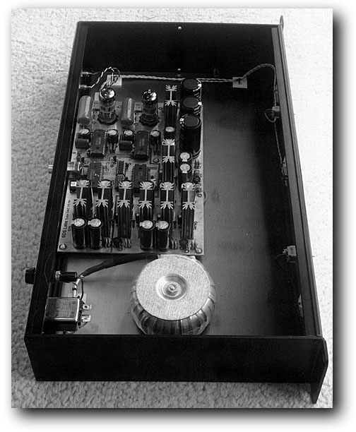
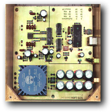
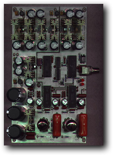
I have already published two of my digital to analog converter (DAC) designs in Positive Feedback Magazine (Vol. 5 #1, Vol. 5 #3). I designed a low cost DAC which uses the Crystal Semiconductor all-in-one stereo bitstream DAC chip. It is a very nice little unit and can be constructed for about $75. The larger DAC is substantially more sophisticated and costs more to build, but the increased complexity and cost are justified when the increased performance is considered. The Big DAC uses the Crystal Semi. decoder chip, followed by one of NPC's newest digital filters. This filter also de-emphasizes the signal in the digital domain (if needed). The output of the digital filter is fed to a pair of Burr Brown PCM-63-K DAC chips. The output of the DACs goes to a passive current to voltage converter (no op-amps or active components to color or distort the sound). The output of the I/V stage feeds the grids of a pair of tubes (6DJ8's or 12AT7's) in an SRPP (shunt regulated push pull) configuration. The total analog signal path consists of a resistor, a tube gain stage, and a capacitor. The signal path is kept so short by the clever use of a resistor for current to voltage conversion (thanks to Peter Campbell for this one), and not using a low pass filter to remove quantization noise. It has been determined that the filter is not needed, as the quantization noise products start at 382 KHz due to the 8 times oversampling. This ultrasonic trash is filtered out by the interconnects, subsequent gain stages, speakers, and finally your ears. There are eight separate regulated power supplies in the Big DAC. each channel has it's own dedicated power source, The digital side of the DAC even has it's own power transformer. Three photos of my prototype of this DAC can be seen by clicking on the items below.
|
|
|
Prototype CS4329 DAC |
Prototype Tube DAC |
|
DAC News I have finally gotten around to getting the big DAC boards professionally made. So now they will have plated through holes, a component silkscreen, and generally be of higher quality that I can do at home. I am going to offer the boards for $125 each, 2 for $200. Sorry for the price increase, but I'm trying to pay for the setup costs that the board house dumped on me. In true capitalist fashion, I'm passing it on to you. With the professionally made boards come a little change in the input circuitry. I added provisions for an input pulse transformer to help isolate the DAC from the transport and lower jitter. If you want to use the traditional capacitor method, you can also do that by putting caps where the transformer went. I have received the circuit boards and they look really really good. Drop me some e-mail to reserve yours now. CS4329 DAC Fix Some people have noticed that the output on this DAC doesn't sit at ground, but rather there is a small DC offset. I tracked this down to a layout mistake on the board. Actually Georg Steiner found it and alerted me to the problem. I've fixed the acrobat file listed below and I've also got a supplemental acrobat file which describes how to fix the DAC if you've built it already. To anybody who has already built the unit, I'm very sorry about the mistake. |
 Tube DAC Transformer Kit Assembly Instructions (252k)
Comments from those who built my Tube DAC
Part Supplier Addresses and Phone Numbers
Positive Feedback Article Text: |
 Download The Files:
|
Here are the three DAC designs saved as *.PDF files. A free Adobe Acrobat Viewer can be downloaded at: |
|
|
|
|
|
Note:The Big DAC design, layout, and parts list are the same as the professionally made boards. The layout assumes plated through holes. |
|