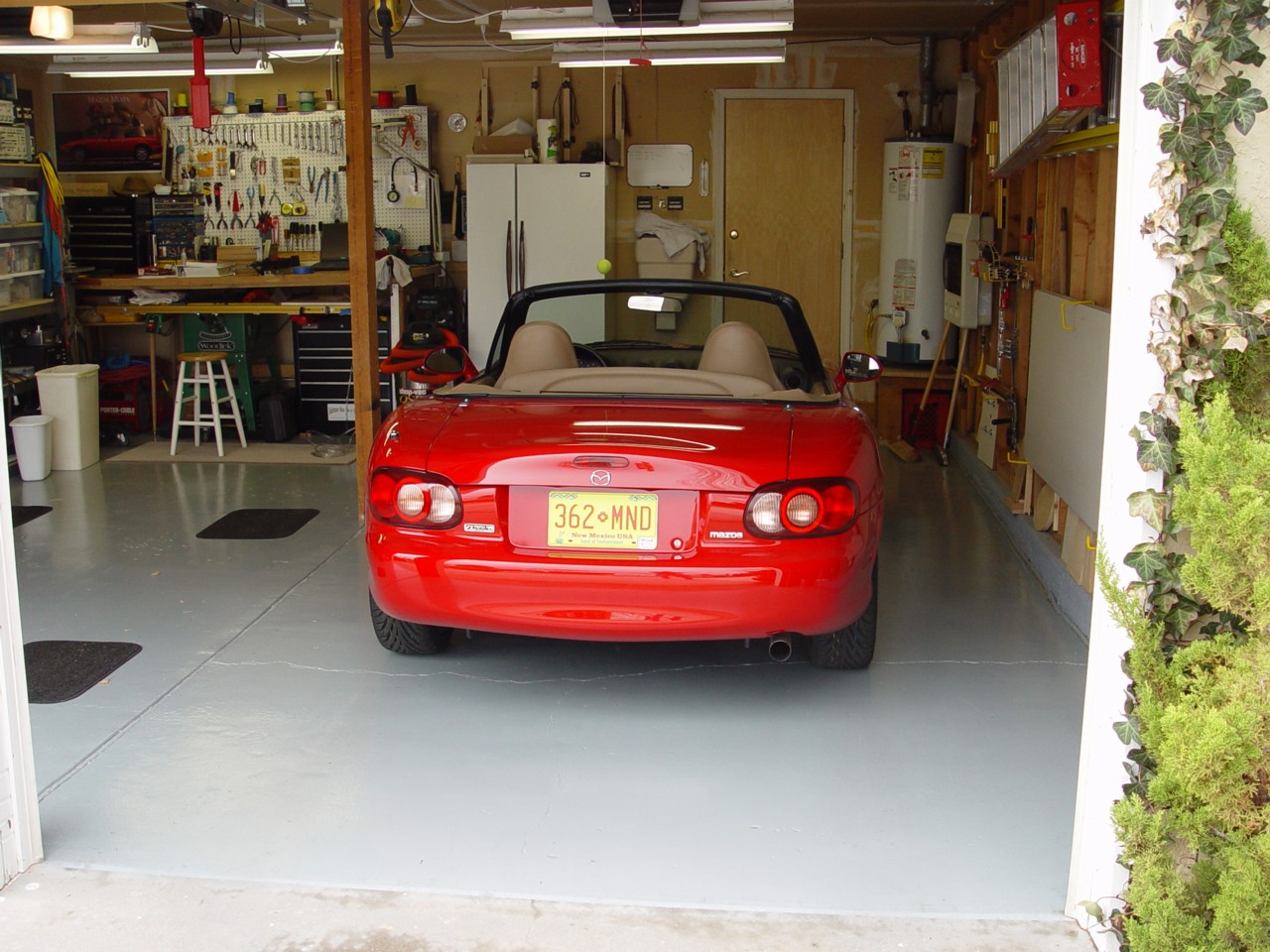

I enjoy working on my cars, like many people, we do it for a sense of control and empowerment as much as for a money savings. To that end, I have designed some tools to allow me to align my cars at home. This page will describe my method, the tools used, and the limitations to it. I will describe the process on my Mazda Miata which is the most complex and highest performance suspension I own.
Your car's alignment can pre-maturely wear tires, or cause undesirable handling if not set properly. My experience with computerized shop alignment racks is not good to say the least. Those machines are designed for ease of use (by low skilled workers), and speed. Accuracy is a lower priority. If you are lucky, you can find a place that will work with you and try to get the alignment numbers you want, but I have yet to find such a place. Are adjustment bolts re-torqued properly? Is your steering wheel straight after the procedure? My experience has been no.
The Mazda Miata has a very sophisticated suspension for a road vehicle. It uses dual "A" arms on each corner with coil-over shocks. The rear wheels have adjustable camber and toe, and the front wheels have adjustable caster. camber, and toe. With so many degrees of freedom, it's easy to mis-align the car, especially at home.
As stated earlier, the three parameters measured in an alignment are camber, caster, and toe. I won't go through those here, but rather refer you to a good paper on the subject (or a Google search should turn something good up) which is a reprint of an SAE journal article by the Hunter corporation who makes the alignment racks I was disparaging earlier. The paper is here. Toe is measured directly from the wheels to a reference line. Camber is a measurement of vertical angle. And caster is indirectly calculated from a pair of camber measurements at known front wheel turn angles.
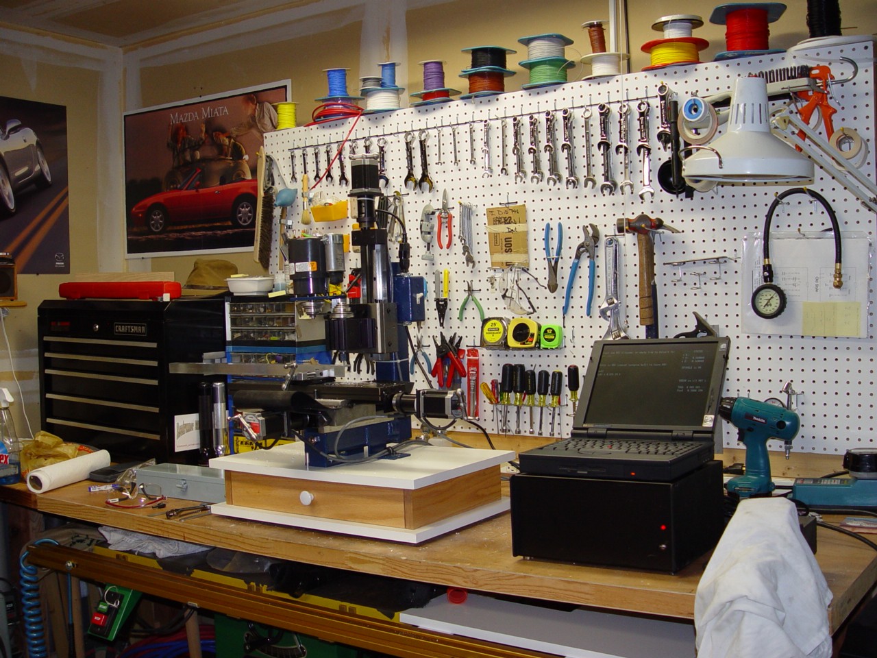
To measure camber angles an accurate method of measuring nearly vertical angles must be used. There are many camber gauges on the market, based on spirit levels, plumb-bobs and such. I didn't want to buy one, favoring making my own very precise one. I also was looking for an interesting project to use my desktop CNC mill (see picture).
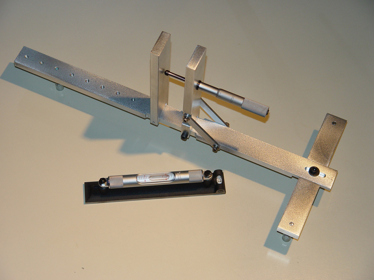
The camber gauge I designed uses a micrometer mechanism to tilt a pivoting shelf upon which rests a machinists spirit level. An inverted "T" with adjustable feet contacts the rim in three places. the feet are adjusted so that they are all the exact same distance from the "T" frame. With the fixture placed on the rim, the micrometer is adjusted until the spirit level reads that the pivoting shelf is level. The reading on the micrometer indicates the camber angle of the wheel. The micrometer mechanism pivot is spaced such that 2mm of micrometer travel equals one degree (when kept near perpendicular). This gauge has an angle resolution of one thousandth of a degree, but it's accuracy is probably more in the neighborhood of one hundredth of a degree. The fixture can accommodate rims from 12" to about 19". A picture of it's maiden voyage is shown below.

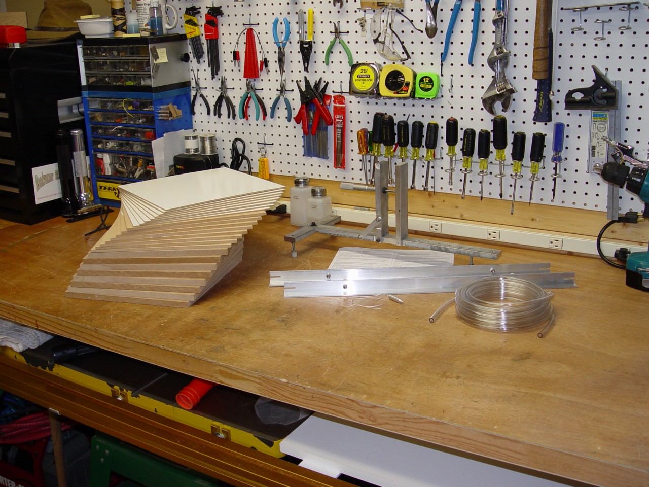
Shown below is a collection of parts used for the alignment. They include wooden spacers, my camber gauge, a length of Tygon tubing, and a small plumb-bob. Also needed is string or fishing line and accurate metal rulers as well as secure stands to attach the string at wheel hub height. The stands I used were a set of jackstands.
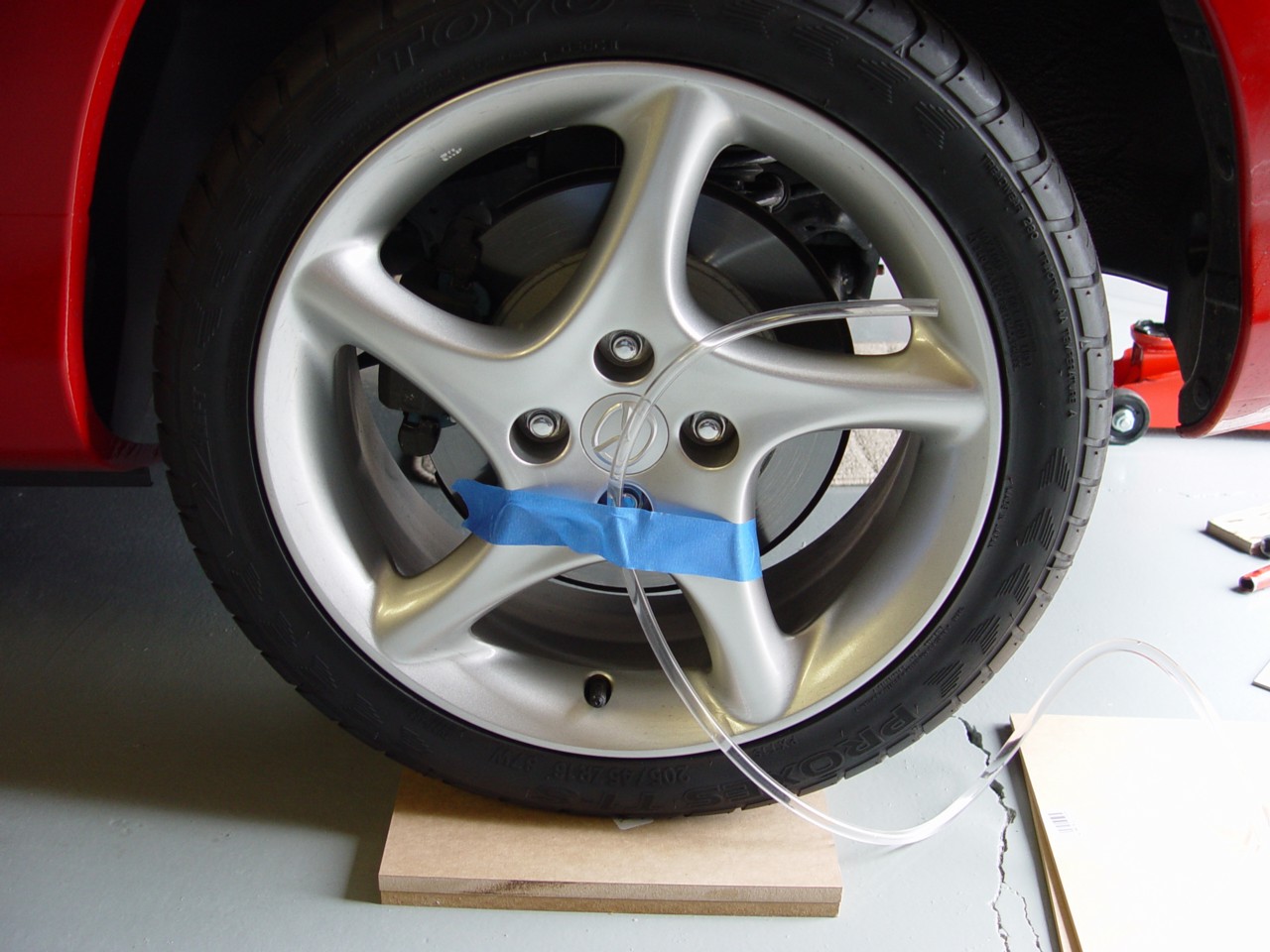
The more astute reader has realized that the camber gauge only reads true camber if the car is resting on a level surface, otherwise the angle measurement is meaningless. This brings up the first element of a home alignment; leveling the car. It's been my experience that level garage floors, and level concrete in general, only exist in mythology. My garage slopes about 1" over the wheelbase of the Miata, and about 1/4" over the width. This means that I can't get good measurements with the camber gauge unless I level the car. I cut one foot squares of 1/2", 1/4", and 1/8" thick MDF and hardboard to use as spacers. I used a length of 3/8" Tygon tubing filled with water to measure the height of each wheel. I used the bottom edge of the dust cap as a mark to set the water level. Various thickness spacers are placed under each wheel until the water within the tube is at the same level on all wheels. I used one wheel as the reference and adjusted the tubing so that the water level as at the dust cap, and took the other end of the tubing to each of the three other wheels and made sure the water matched the same point on each wheel. If you jack the car to place spacers under the wheels (rather than driving up on them), make sure you jounce the suspension to settle it before making any measurements (this isn't necessary to check for level). It's good to note that some sort of slippery surface must be used under the front wheels. The front wheels must be turned to measure caster and the suspension shouldn't be bound up trying to make that turn. I put a pair of the 1/8" hardboard spacers under each front wheel which were quite slippery against each other.
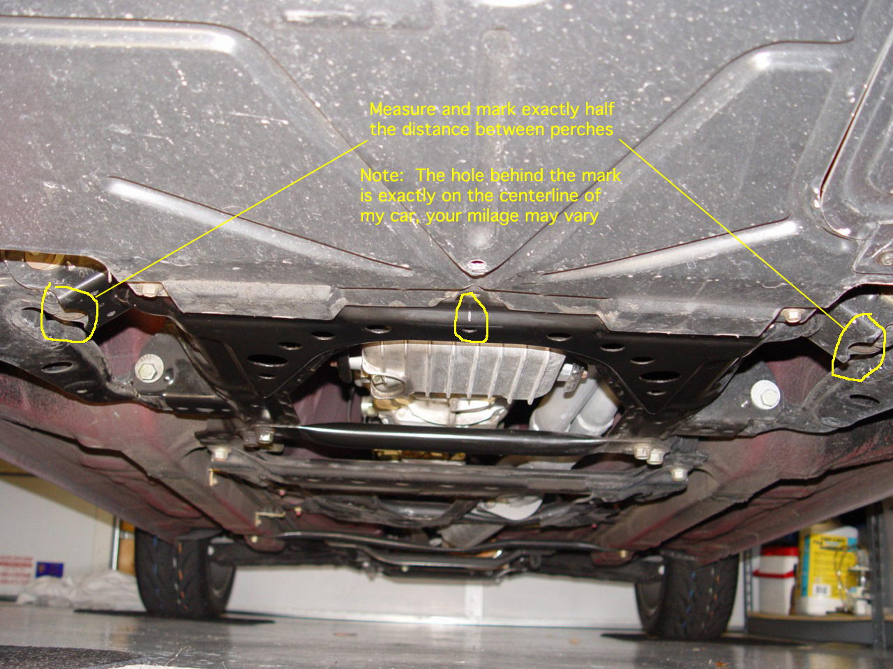
The key to keeping everything lined up and not going down the road sideways is to define or measure the thrust-line of the car and align each wheel to this thrust line. The desired thrust line is the center line of the car. This is measured, not from the body, which isn't positioned accurately enough with respect to the suspension pivots to be useful. But rather to the suspension pivots themselves, and the midpoint between them. I marked the thrust line by jacking the car up and measuring between the suspension perches and then scribing a center line between the perches on something which should be visible when the car is on it's wheels. The marks I used can be seen in the two pictures below. Click on the pictures to see a larger version

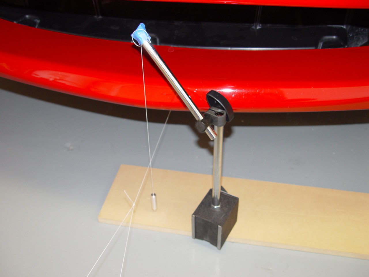
With the car leveled, the thrust line must be made visible and usable. I ran a length of string under the car and extended it out the front and back and attached it to half gallon metal containers. The string needs to be directly under or touching the thrust line marks. I used a small plumb-bob in the back of the car and a small machinist's square in the front to insure this. This will then be my thrust line by which all wheels will be aligned to. Note: you shouldn't use your car's body as a reference (IE Mazda emblem) because the body tolerances are actually quite loose and your body may not be centered on the suspension centers.
The issue is now that this string is impossible to measure off of, it might as well be buried under your garage. The next thing you will need is another pair of strings attached to jack stands or something similar that will get the strings up to hub height on each side of the car. You place these strings parallel to the sides of your car pulled taught and using a small plumb bob and a ruler or gauge board, measure the distance from the thrust line string where it exits the back of the car to one side outer string using the plumb bob. Remember that distance and move the ruler to the front, and do the same thing, adjusting the front jack stand to try to get the distance the same. Repeat until you are satisfied that the two strings are parallel. Then repeat for the other side of the car. You want your outside strings to be about 9 inches away from your wheel centers so you can turn your front wheels without hitting the strings. Shown below is a pair of pictures showing the use of a plumb-bob (and dial indicator holder) to insure the strings are parallel (click for larger images).

The lower "A" arms on all corners of the car are mounted to the subframe with pairs of eccentrics. The toe, camber, and caster are adjusted with these eccentrics turning them the same direction or opposite directions. The eccentrics are held in place with a bolt with flat sides and a cinch nut. The nuts must be loosened for adjustments to be made to the eccentrics. The nuts are held in place with 55-70 ft-lbs of torque (and who knows how much if someone else aligned your car in the past). They can be damn near impossible to loosen with the car on the ground. You may want to loosen them before leveling, but don't loosen too much, only enough that you can finish loosening them when ready to adjust. Shown in a table below is my target alignment numbers, these are similar to the numbers provided by Miq Millman which I believe descended from Lanny Chambers' numbers. These numbers should be a good compromise between performance and tire life.
| Left | Right | |
|---|---|---|
|
Rear Camber: Toe: |
-1 deg 0 toe_in |
-1 deg 0 toe_in |
|
Front Camber: Caster: Toe: |
-0.8 deg 5 deg (or max) 1/16" toe_out |
-0.8 deg 5 deg (or max) 1/16" toe_out |
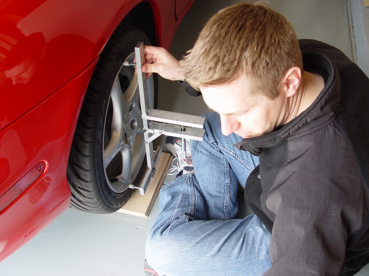
I recommend starting by adjusting the rear wheels. They are a lot easier and will allow you to get the hang of it on a more simple adjustment. the two eccentrics control toe and camber. If you move both the eccentrics the same direction by the same amount, you are only changing camber. If you move them equal and opposite directions, you are essentially only changing toe. This is a tedious process and benefits from the help of a friend (see picture below for an example of a friend), but is not necessary. Camber is measured with the camber gauge, and toe is measured by taking careful measurements from the wheel rim to the reference string at the front of the rim, then at the back (seen in the friend picture below). With careful stringing, fine string, and careful measurements, each toe distance measurement should be accurate to within a 64'th of an inch. Multiple measurements will also reduce the uncertainty. When camber and toe is adjusted to your liking, tighten down the locking nuts on each eccentric. It's a good idea to hold the bolt with a wrench to prevent movement while the nut is being tightened, although after it gets fairly tight, the wrench on the bolt can be removed.
Remember that your strings are your accuracy and your reference. you are only as accurate as the placement of the strings and your ability to measure to them and not disturb them. It's really easy to bump the strings, it's a good idea to check their placement from time to time. Check your strings when you finish a wheel, it's a good idea.
After you have one back wheel adjusted to your liking, adjust the other back wheel to match. the exact numbers are not as important as matching the numbers left to right. you may find that you can't get the exact numbers you are striving for (particularly if your car was hit or lowered). You need to make both sides match as best as possible and that can mean relaxing some of your desired numbers.
The front wheels are a bit more involved. Where the back eccentrics worked with equal effect at camber and toe, the front ones are a bit more single purpose with a small amount of crosstalk. The eccentrics control camber and caster, the turnbuckle ends of the steering rack linkages control toe. The front eccentric mainly adjusts camber. The rear eccentric mainly adjusts caster. As I stated earlier, caster is measured from a pair of camber measurements at two wheel turn positions. the formula is:
Caster (deg) = (180 / 3.1415) * [(camber1 - camber2) / (turnangle1 - turnangle2)]
The turn angles must be equal and opposite. for my measurements I turn the wheels almost one complete revolution which was 24.6 degrees. This made turn angle measurement easy. I measured the distance from the front edge of the rim to the string and then the back edge of the rim to the string, and the difference between these two distances divided by the rim diameter where measured (17" in my case) is the sine of the angle. By making the distance difference 18cm each time, the angles were the same every time. I estimate that based on our distance measuring ability we have an angle uncertainty of about 0.1 deg. This combined with a camber measurement uncertainty of about 0.01 deg (neglecting leveling issues), we then have a caster uncertainty of 0.03 degrees. Leveling uncertainties can swamp this caster uncertainty as can car front end drift with wheel turn (an issue with all alignment setups).
So a front wheel adjustment involves setting camber and caster with the eccentrics while the wheel is facing forward, snugging down the eccentric nuts, and turning the wheels to the right and left making a camber measurement at each, then using the formula above to calculate caster. This is repeated until the desired numbers are reached. If you are not confused or overwhelmed easily, both front wheels can be adjusted at the same time, then a left steering wheel turn can be used to measure both left and right wheel cambers cutting the number of wheel turns in half. However to get the exact angle for camber measurements usually requires slightly different steering wheel positions for left and right wheels (unless toe is exactly zero which is unlikely with camber adjustments).
When front camber and caster are set to your liking, it's time to work on toe. Front toe is a relative thing, when driving straight down the road, front toe is balanced (assuming the rear wheels are aligned to the thrust line). But in order to make the steering wheel centered when driving straight, the toe for each wheel much match when the wheel is straight now. Set the steering wheel straight and measure the distance to the reference string at the front and back of the rim. Adjust the steering turn buckle for that wheel until the desired toe is achieved. Repeat for the other side. Tighten the locknuts on the turnbuckles.
review your notes and make sure you are happy with your alignment tolerances and actual alignment numbers. Now is the time to change them while you still have your reference strings. If you are happy it's time to finish up...
Congratulations!, you've aligned your car, but don't drive off yet...
You need to tighten the eccentric nuts. tighten them as much as you can with the car in place, then jack the car up and tighten to 55-70 ft-lbs using a torque wrench. the front eccentric nut on the front wheels can't be reached with a torque wrench because the steering rack linkage is in the way. Tighten it down as much as you can.
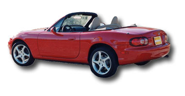
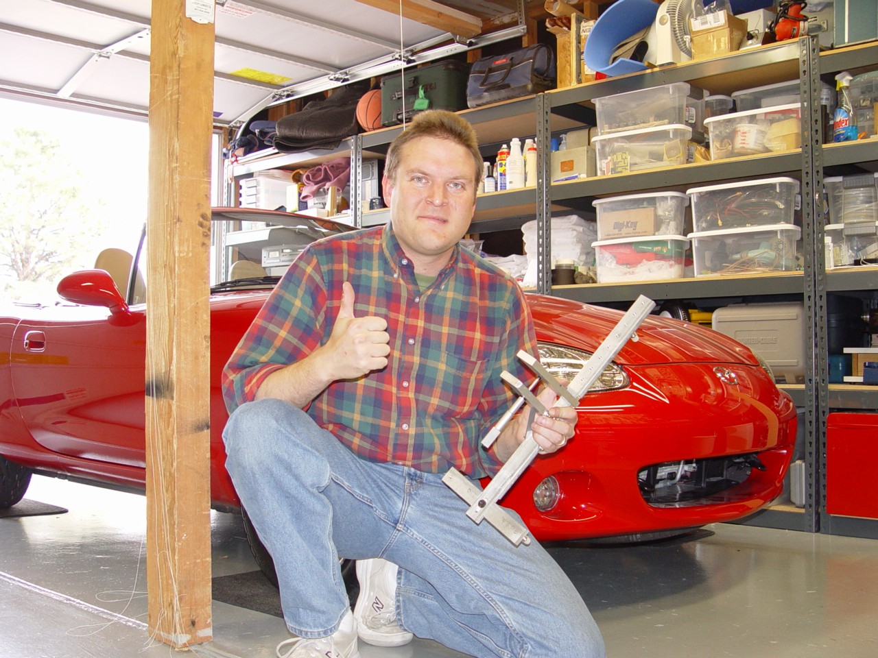
A very happy owner just back from a ride with a much nicer alignment than factory stock
My actual numbers:
| Left | Right | |
|---|---|---|
|
Rear Camber: Toe: |
-0.89 deg 0.0 toe_in |
-0.89 deg <0.053 deg toe_in |
|
Front Camber: Caster: Toe: |
-0.86 deg 5.23 deg 0" toe |
-0.89 deg 5.23 deg 0" toe |
NOTE: This is a time consuming process, don't expect to do it in an hour. This took me (and my friend) 6 hours to complete the process. We were very careful with measurements and adjustments, we took our time and repeated measurements. I think we could do it in about 3 hours if we were to do it again, but budget a whole day. Find a good place to work with lots of space and good light. And take a break if you get frustrated.
Keep the shiny side up...